Electrical Energy Systems Laboratory
Istanbul Technical University
Electrical Energy Systems Laboratory
Istanbul Technical University
A large number of transformers operating in electricity grids regulate the voltage dynamically when operating conditions change. For instance, when the load curve is high in the morning and the potential in the grid tends to decrease, regulators should keep the voltage level by changing the turn ratio of tapped windings. The on-load tap changer (OLTC) can keep the grid potential at a sufficiently constant level. Since the OLTC is the only moving component of the transformer, it is particularly vulnerable. Approximately half of all transformer failures are due to failures in the OLTC. Different reasons can cause these failures and various failure modes are important under different operating conditions. Such failure modes contain mechanical wear of the contacts, excessive oxidation, coking, fretting and creep. The OLTC adds the possibility to regulate the output voltage of a power transformer by changing the turn ratio whilst the transformer is under load. The large currents and voltages under which the transformer operates impose great demands on the contacts of the OLTC. Most of transformers are generally in operation for at least 30 years with only minor maintenance and nowadays a large number of in-service transformers are at the end of their life. Therefore, an online monitoring method must be deployed to assess the condition of different parts of transformers. A tap changer can vary the number of turns in one side of the transformer and thereby, change the transformer ratio. Normally, this can vary between 10-15% in steps of 0.6-2.1%. In normal grid situations the OLTC is operated around 10 times per day, but this number can be much higher for example industrial applications. It might also not be operated at all for long periods of time or even years.
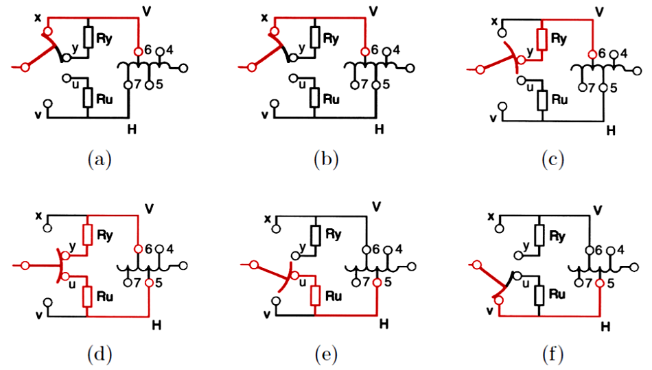
There are a number of steps performed in sequence to complete a switching operation. Below figure shows the switching principle of an OLTC with a diverter switch and a tap selector switch. The contacts x and v, called the main contacts, are the two possible states for the diverter switch while V and H are the two selector arms which select the one of the numbered tap contacts to choose the number of turns that are presently used of the regulating winding. There are also two auxiliary contacts, y and u, each one with a resistor. Considering figure 1, the sequence to change regulation winding from tap position 6 to tap position 5 is as follows:
Here, at the electrical energy systems laboratory, we have been working on new ideas regarding the OLTC condition monitoring since 2013. We are well aware of several solutions already presented and produced all around the world. Up to the present, several parameters have been used to assess the operating condition of OLTCs with different levels of accuracy and reliability. There are offline methods as well as online methods considering the condition-based maintenance strategies. However, it is expected that the OLTC condition diagnosis will move away from on-line centralized to real-time distributed approach in the near future in the frame of smart grids. There are also high demands of more accurate and more reliable measurements using modern data processing techniques. Our activity is covering local monitoring units as well as central control system developments based on innovative ideas with respect to the requirements of real-time distributed measurements considering smart grid strategies. Here, our main objective is to deliver our solution for the OLTC condition monitoring both in hardware and software levels in the near future.
Maschinenfabrik Reinhausen (MR) is a leading manufacturer with decades of experience in voltage regulation area.
Its productions and services include:
-On-Load Tap-Changers (OLTCs),
-De-Energized Tap-Changers (DETCs),
-Voltage Regulators & Oil Filter Units,
-Monitoring Systems,
-Transformer Accessories,
-Voltage-Regulated Distribution Transformers,
-Power Quality Management® Solutions,
-Power Composites® - Hollow Insulators,
-Asset Management Services.